Original URL: https://www.theregister.com/2010/05/21/paris_radio_kit/
PARIS flashes some radio goodies
Beacon and GPS kit unveiled
Posted in Science, 21st May 2010 11:02 GMT
It's with great pleasure that the Paper Aircraft Released Into Space (PARIS) team today officially welcome aboard radio man Steve Daniels (callsign G6UIM), who's put together some tasty kit for the project and will be our in-the-field radio operator when launch day arrives.
![]() Steve's been building computers since 1979, when he assembled his first UK101 while still at school.
Steve's been building computers since 1979, when he assembled his first UK101 while still at school.
Following an apprenticeship and B-Tec in Electronics, Steve worked on TWT (Travelling Wave Tubes) high power microwave amps, and following his conversion to the world of amateur radio in 1983, started running a radio linked BBS packet system, which he describes as "sort of amateur radio internet, before the internet was publicly available".
Since 1991, Steve's been working with PCs and networks in an educational environment, as well as helping special needs kids.
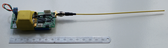
And since last month, he's been slaving over the PARIS main payload radio beacon and Vulture 1 GPS board. Here's the beacon:
![]()
This acts as a back-up for the GPS tracker unit we'll be using to follow and recover the main payload. It transmits PARIS BEACON V1 3.83E VØ 3.85 E in morse and then beeps for 0.5 seconds every 4.5 seconds and after 50 beeps repeats the beacon text.
The parts, supplied by Greg Clark at Big Red Bee, are:
- CC1050 transmitter module from Texas Instruments
- 16LF688 Pic from MICROCHIP
- RF3861 amp from RF MicroDevices
- 4.2V 200mAH Li-Po battery
This is the crucial Vulture 1 GPS unit, which will enable us to track the flight via radio and recover the aircraft:
The parts comprise:
- CC1050 transmitter module from Texas Instruments
- 16LF88 Pic from MICROCHIP
- Trimble Lassen IQ GPS module
- 4.2V 750mAH Li-Po battery
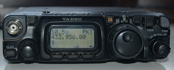
Here's where the transmitted GPS data is captured - Steve's Yaesu FT-817 Multiband Multimode transceiver:
The received data can then be handily displayed on a laptop running the APRSIS32 software, created by Lynn W Deffenbaugh (callsign KJ4ERJ). Click on the pic for a bigger version:
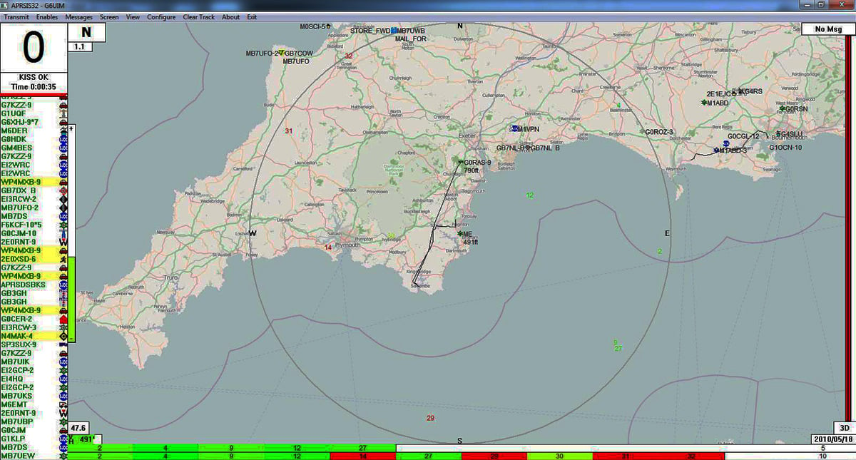
Our backroom boys are currently working on a way to get the data onto a live Google map on El Reg, so that readers can follow our forthcoming test and, when the time comes, the flight of the Vulture 1. We've already done this for the main payload GPS tracker, and it works a treat, as you can see here.
We'll give you a heads-up before our next test, which should make for entertaining viewing.
And that's just about it for now. The next couple of pages give details of the beacon and GPS set-ups, as provided by Steve. ®
Additional PARIS resources
- New to PARIS? We have a basic mission summary here (pdf).
- Our YouTube channel - currently featuring a few camera tests.
The beacon set-up:
![]()
Frequency: Enter the frequency desired, in Mhz. The valid range is between 420-450Mhz.
Output power: Enter an integer between -20 and +24dbm.
Beep Duration: Length of a ‘beep’ in 100 ms increments (3 = 300 millisecond). Range is 1-255.
Beep Space: Length between beeps in 100ms increments (47 = 4.7 seconds) Range is 1-255.
Number of Beeps: Number of beeps between ID String transmissions.
Beep Frequency: Audio frequency (in Hz) of the ‘beeps’.
Morse ID Frequency: Audio Frequency (in Hz) of the Morse code transmissions.
ID String: Message to be transmitted via morse code.
Battery: The battery voltage as read by the A/D converter.
TX ON ViD: Battery Voltage on Transmit.
TX OFFVID: Battery voltage is when not transmitting.
Skip low V shutdown: If checked, Low voltage check and shutdown is not enabled.
The GPS set-up:
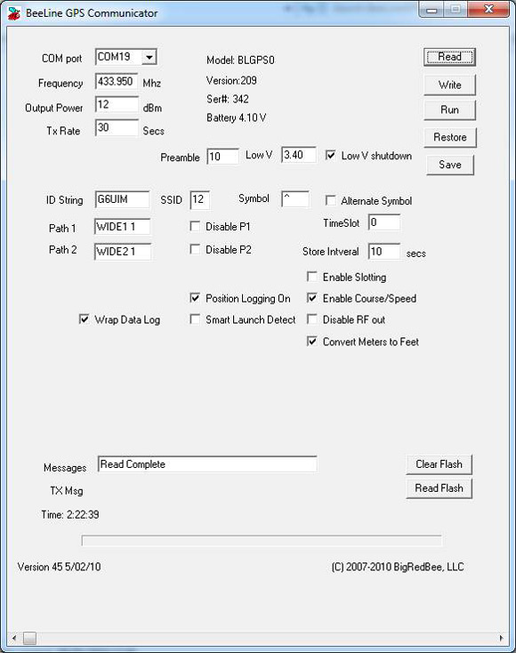
Frequency: This is the RF carrier frequency the packet will be sent out on. Possible values are 420-450 Mhz.
Output Power: Set between -10 dBm and 12 dBm.
Packet Interval: Number of seconds between packet transmissions.
Store Interval: Number of seconds between writes to on-board memory.
Preamble: Number of IDLE bits sent before start of packet data.
TimeSlot: Number of seconds to delay if slotting is enabled.
ID String: Your amateur radio callsign. Not more than 6 characters in length.
SSID: The SSID in the APRS packet. The default is 1, possible values are 1 thru 15.
Symbol: The symbol character in the APRS packet. The default is ‘-‘.
Enable APRS Packet format: When this option is checked, APRS position packet will be transmitted.
Position Logging On: Position and altitude data will be logged into o-board memory.
Enable Slotting: Turn Time Slotting ON. See below.
Enable Course/Speed: The course and speed are transmitted as part of the data packet.
Disable RF Out: Disables RF transmissions.
Wrap Data Log: When set, data is overwritten starting at the beginning after the end is reached.
Path: Each is 7 characters in length. AX-25 digipeating protocols.
Low V Shutdown Enable: Low voltage battery protection.
Read Data: Data memory is read from GPS and stored to disk (.kml file).
Smart Data logging:
Power On: When the GPS is powered on, it enters the base altitude state.
Base Altitude: GPS begins looking for a base altitude from the GPS engine. When it detects 32 consecutive valid GPS position reports, each with four or more satellites in view, the BASE ALTITUDE is recorded.
Launch Detect: The GPS begins looking for a launch condition. When three consecutive GPS positions report, each with four or more satellites in view, that is 100 meters above the Base Altitude, the state transitions to fill memory.
Fill Memory: The GPS records latitude, longitude and altitude data, wrapping when it reaches the end of memory, and continues writing up until the 32 samples before the sample where launch detect was stored. When memory is filled, the state transitions to full: While in this state the altitude is preceded with the ‘V’ character.
Full: No more samples are stored into memory. While in this state, the altitude is preceded with the ‘F’ character. Data packets are transmitted continually.
The normal progress through the state machine will be as follows:
* : Detecting base altitude.
^ : Waiting for launch.
V : Launch detected.
F : Memory full.